Examining In-Situ Relative Humidity Probe Testing
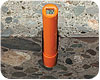
The purpose of drilling to the specified depth is to expose the concrete at that depth, so moisture can migrate out of the concrete to accumulate and equilibrate. Photo courtesy Wagner Electronics.
In-situ relative humidity (RH) probe testing can be tricky. On many jobsites where moisture testing is being done, I have encountered situations where several types of relative humidity (RH) probes have been used with different results. I recall one particular jobsite where two testing companies were testing virtually within feet of each other and the readings showed a 12% difference in test results.
Why the huge difference? And which result do you believe? With my almost half-century tenure in the flooring industry, I have seen moisture testing evolve from educated guesswork to a very scientific approach. In July 1996, Dr. Göran Hedenblad of the Lund Institute of Technology, Stockholm, Sweden, performed experiments measuring the relative humidity within concrete by performing in-situ testing at different depths within a concrete slab. His work showed that there exists a relative humidity (RH) gradient within a slab that had its surface exposed.
The findings showed that RH increased as the testing depth in the slab was increased. He went on to show that after the concrete slab was covered by a flooring material with minimal permeability (thereby preventing moisture from migrating out of the concrete surface), the RH gradient equalized to an average RH throughout the slab that is equal to the RH at 40% depth of an uncovered slab drying from the surface only (resting directly on a vapor retarder), or equal to the RH at 20% depth of an uncovered slab drying from both top and bottom.
These findings became the foundation and basis for the development and publication of ASTM F-2170, Standard Test Method for Determining Relative Humidity in Concrete Floor Slabs Using in-situ Probes. The purpose of the F2170 standard is to provide a standardized practice for which to perform an RH measurement within the concrete.
The intent is to provide a standard practice to measure the RH at a specified depth, as well as how to drill the hole, insert a liner into the hole for sealing off the sidewalls of the concrete, the placement of a seal at the top of the liner to seal off the internal environment, the equilibration of the internal environment RH and the accuracy of the testing instruments employed in the measurements.
Drilling the Hole
The first step is to determine the thickness of the slab, as the hole to be drilled must be depth specific. Taking a reading in too shallow a spot will yield a drier result; too deep will yield a wetter result. The F2170 standard clearly specifies the drill-to-depth from top of slab position: 40% for slab drying from top only, and 20% for slab drying from both sides.
The purpose of drilling to the specified depth is to expose the concrete at that depth, so moisture can migrate out of the concrete to accumulate and equilibrate within a sealed-off measuring environment. This will allow a subsequent measurement to determine the equilibrated RH level at the specified depth. Since the concrete has an RH gradient throughout the depth of a slab that has an exposed surface, it is paramount to measure the correct RH at the correct depth.
Next, the use of the proper type of drill is critical. A two-fluted carbide bit will tend to cut a hole that is slightly out of round and will not allow a proper seal of the sleeve. A four-fluted bit will cut a much rounder hole.
Cleaning the Drilled Hole
After the hole is drilled, it must be thoroughly wire-brushed and vacuumed. It is imperative to remove all dust and debris as any leftover fine dust particulate will contaminate the sensors and render them inaccurate.
Inserting the Liner
The F2170 standard clearly specifies to insert the liner to the bottom of the hole. Place a rubber stopper in the upper end of the liner and then seal around the liner at the concrete surface with joint sealant, caulk or a gasketed cover. Section 6.2 defines the hole-liner as “plastic or non-corroding metal tubes with an inside diameter not more than 0.04” (1 mm) greater than the probe’s external diameter.” The liner must be of sufficient length to seal the hole to the desired depth.
The main purpose of the liner is to isolate the very bottom of the concrete at the specified depth of the drilled hole to provide a measurement environment to perform the RH testing. Further, the purpose for the liner is to seal the sidewalls of the concrete off from the exposed concrete at the open bottom of the liner, and to create a seal at the concrete surface to prevent moisture from migrating out of the drilled sidewalls and out the surface. This would provide a “drying out” mechanism for the local concrete slab area being tested.
Calibration of Probes
All relative humidity probes must be calibrated for accuracy on a regular basis – a minimum of once per year. Dust and everyday usage can throw off the calibration of probes. Many parties paying for moisture testing will ask for your calibration certificate.
Equilibration of Probes
The placement of the probe into the sleeve requires the time necessary for the probe to reach equilibrium with the slab. The time required varies depending upon the type and condition of the probe. The F2170 standard specifies the need for the measurement sensor or probe to come to thermal equilibrium with the concrete: “Probe shall be at the same temperature as the concrete before reading,” and for the sleeve environment to come back to equilibrium once the sleeve is uncapped and a measurement sensor or probe is inserted into the sleeve.
The F2170 standard clearly specifies to check for drift, as the “meter reading must not drift more than 1% relative humidity over 5 minutes.” Furthermore, the standard states, “Equilibration may take several hours to several days depending on factors such as the initial temperature difference between probe and concrete.”
Dead Volume Measurement
Dead volume means the volume of air that is being measured for RH. Since there is an increase of the RH gradient as one goes down into the slab, the question becomes whether the sleeve is allowing a true measurement at the 40% level or a diluted measurement. If the sleeve is allowing RH to be diluted, the dead volume of RH to be measured from other levels of the hole is going to be lower than if it were taken at the prescribed 40% level.
Because some current RH measurement systems do not take into account the existence of a humidity gradient within a sealed sleeve, and many testers are using the 1% RH Drift per 5 minute equilibration rule to determine when a sensor has been adequately equilibrated, concrete slabs are often determined to be ready for a floor installation when in fact the slabs contain a much higher level of moisture than is appropriate for floor installations.
ASTM F2170 committee members are currently undertaking testing to identify the best way to modify the F2170 standard, so RH testing instrument manufacturers will have a better definition of a well-designed sleeve/sensor system, and provide flooring inspectors a better standard of measurement practice to more accurately determine the true moisture content of a concrete slab. We can expect a new version of the F2170 standard to be published sometime in the near future with appropriate modifications.
The manufacturers and installers of flooring materials that have extreme moisture sensitivity need accurate testing results; epoxy terrazzo, rubber, vinyl tile, wood flooring and adhesive manufacturers all need to strive for the most accurate measurements.
Looking for a reprint of this article?
From high-res PDFs to custom plaques, order your copy today!


 test on a concrete slab using in-situ probes")


